Phase diagrams 2
(4) Series LR circuit
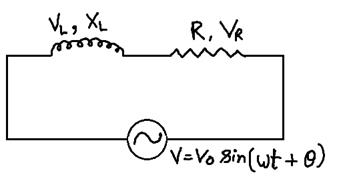
V = (VR2 + VL2)1/2
VL = I XL
VR = I R
V = I Z
V = (V2R + V2L)1/2
I Z = (IR)2 + (I XL)2)1/2
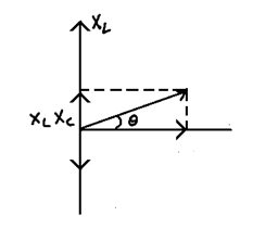
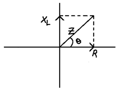
Z = (R2 + X2L)1/2
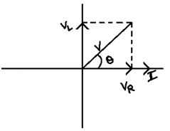
Also tanθ = (VL/VR) = (I XL/I R) = XL/R
Phase difference θ = tan-1(XL/R)
The nature of circuit in Inductive as voltage in leading current by angle θ
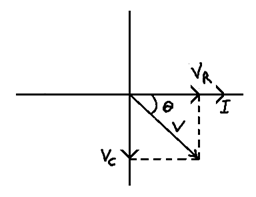
(5) Series CR circuit
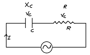
V = (VR2 + Ve2)1/2
tanθ = VC/VR
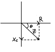
Z = (R2 + XC2)1/2
tanθ = XC/R
Phase difference = θ = tan-1 (XC/R) or tan-1 (VC/VR)
The nature of circuit is capacitive as voltage is lagging current by angle θ
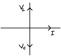
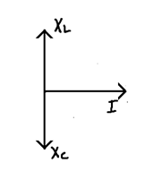
(6) Series LC circuit
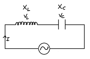
V = VL - VC  θ = +π/2
Or
V = VC - VL θ = -π/2
Z = XL - XC θ = +π/2
Or
Xc - XL θ = -π/2
When VL = VC Z = 0
Phase angle  Arbitrarily
V = I Z
(7) Series LCR circuit
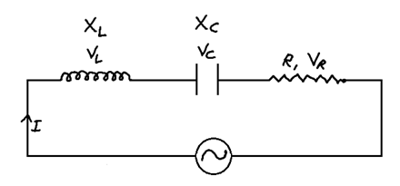
VL > VC
V = (VR2 + (VL– VC)2)1/2
tan θ = (VC – VC/VR)
If VL > VC Inductive nature
VC > VL Capacitive nature
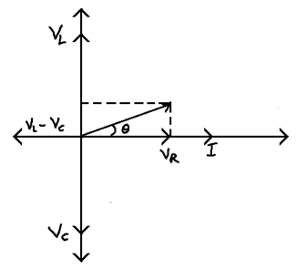
Z = (R2 + (XL – XC)2)1/2
tan θ = XL – XC/R