Half Power Frequencies and Quality Factor
Half Power Frequencies and Band width
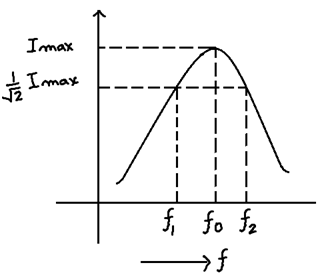
Half power paints are those points on the frequency axis where the current reduces to (-1/√2) times current at resonance. In other words power at such points reduced to (1/2) of the power at resonance.
Band width:- The difference in angular frequencies corresponding to half power paints is known as band width.
Δω = ω2 – ω1
Broader the band more flow of information
Quality factor of a coil is defined as ratio of reactance of capacitor or inductor to the resistance of resistor.
Q = Lw0/R
It is dimension less quantity. It increases with decreases with resistance of the coil. For an ideal coil R = O Q = ∞
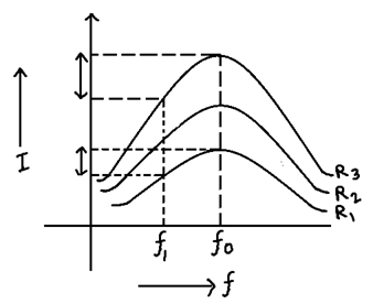
∴ R3 < R2 R1
As f0 is same for all 3 graphs ∴ LC is also same only R value changes.
With decrease in resistance Imax increases ∴ Resonance curve become sharp.
As shown in diagram a sharper resonance curve is able to produce large difference in the currents corresponding two closely lined frequencies.
On the other hand of if resonance curve is flat then almost equal currents are produced for two closely lined frequencies. A sharper resonance curve is therefore able to distinguish clearly b/w two closely lined frequencies hence it has better selectivity and higher quality.