Behaviour of AC with different Components
Behaviour of AC with different components
(1) Pure Resistance
I = e/R
I = e0sin t/R
t/R
I = I0sint e = e0sint
Comparing voltage and current equation, we find that there is no phase difference between voltage and current.
The graph depends upon value of R
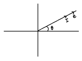
E and I are Parallel as shown in Phasor diagram
(2) Through Pure INDUCTANCE
e = L (dI/dt) (applied)
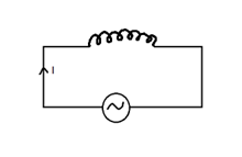
e = -L (dI/dt) (Back)
dI = (e/L ).dt
dI = (e0/L) sin t. dt
Integrating both sides we get
I = (-e0/Lw)cos t [ I = max when cost = 1]
I = -I0 cost I0 = e0/Lw
I = -I0 cos t
I = -I0 cos t
= -I0 sin (π/2 – t)
I = I0 sin (wt – π/2)
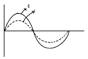
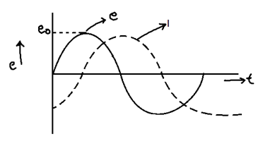
Comparing E and I equations, we find that there is a phase difference of (π/2) b/w E and I such that voltage leads the current by (π/2)
As  = π/2 as we can also say that V and I are mutually perpendicular.
 \
\
Inductive Reactance (Xc)
It is the opposition offered by inductance to the flow of AC through it.
From the equation
I0 = e0/Lw
We find that LW has dimensions of resistance it in known as Inductive reactance.
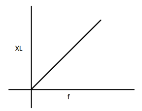
XL = Lw unit  ohm
ohm
XL = 2π�f.L
If f = 0 XL = 0
 The inductance offers no opposition for steady DC. It offers greater opposition for AC with high frequency
 \
\
Physically the value dt changes quickly
e = -L(dI/dt)
so e is large
(C) through Pure CAPACTANCE
e = q/c
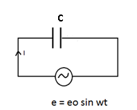
q = ec
q = e0 sin t C
q = e0C sin t
dq/dt = e0Cw cos t
I = e0 Cw cos t
As max value of cos t = 1 Imax = e0 C
I0 = e0 C
I = I0 cos t
I = I0 cos t
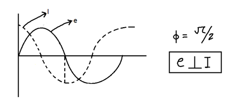
I = I0 sin (t + π/2)
Comparing e and I equation we find φ = π/2 ∴ in case of pure capacities current leads voltage by π/2
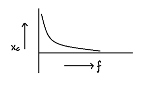
Capacitive Reactance (Xc)
I0 = e0C
I0 = e0/(1/C)
Above equation suggest that (1/C) has dimensions of resistance known as capacitive reactance
Xc = 1/C unit ohm
Xc = 1/2πfC
If f = 0 then Xc = ∞
Capacitor perfectly blocks steady DC.
With increase in frequency Xc decreases